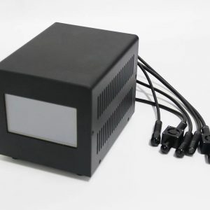
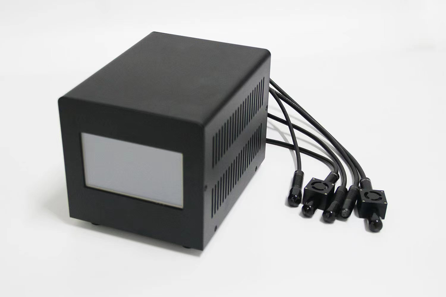
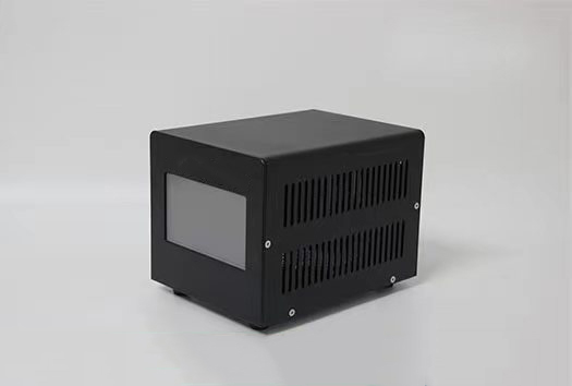
1. Touch screen display
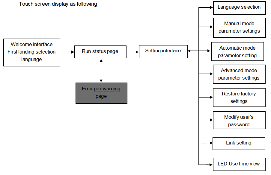
Touch screen display as following
2. Touch screen’s screen switch description
1.Welcome interface
When you turn on the host at first time , it will jump out of the choice of language interface, select end customer’s required language, the system will record the user automatic language selection, when second time to enter the system, the welcome page will be displayed and directly jump to the corresponding language environment, if users need to change the language, the language can be re-selected on setting page.

2.Operating state interface
The state interface is a table that shows the operating parameters of the light source. Display contents include channel running state, running mode, working intensity, running time and working temperature.
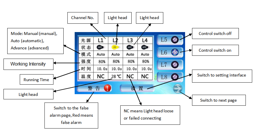
Eight Channels Running Interface Second Page
Error pre-warning interface
The current interface used to display a number of LED error messages, when the error mark behind the listed projects was lighted, the user need to contact our company to help eliminate the trouble and ensure the normal operation of the device.

EightChannels Pre-warning Interface
Set main interface
Enter the main interface by initial password (1234), in the settings of the main interface, users can choose the language , restore the factory settings, modify the password, view LED use time etc. And the pulse and level setting of each channel is also completed in this page, after modifying the working state of the light head, need to save the settings in order to make the setting become effective

- 1Eight Channels Setting Interface First Interface
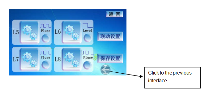
EightChannels Setting Interface Second Interface
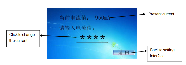
FactorySetting Interface
In the Link Setting Interface, users can link numbers of channels to control easily. Users only need to open link switch, then operating one light head to control others.

LinkSetting Interface
Manual, automatic, advanced settings page
After entering each channel’s specific parameters setting page , there are three modes can be selected, select the appropriate mode to set specific parameters, after setting need to click “ Save setting ” on the lower right corner to make the settings effective, if click “ Returning “ on the upper right corner will not save the settings and configuration is still the old one
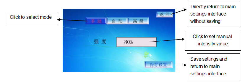
Manualmode settings interface
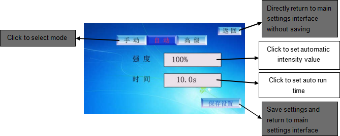
Automaticmode setting interface
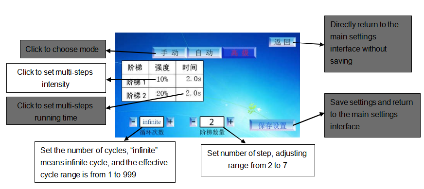
Advancedmode settings interface
⑥ LED Working time state interface

5.1 Eight Channels Using Time Interface
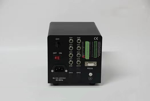
○7 The corresponding serial number and definition of each pin are as follows:
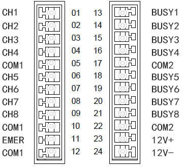
| NO. | Signal | Definition |
| 1 | CH1 | Channel 1 start and stop signal |
| 2 | CH2 | Channel 2 start and stop signal |
| 3 | CH3 | Channel 3 start and stop signal |
| 4 | CH4 | Channel 4 start and stop signal |
| 5 | COM1 | Input common ground, the internal has been grounded |
| 6 | CH5 | Channel 5 start and stop signal |
| 7 | CH6 | Channel 6 start and stop signal |
| 8 | CH7 | Channel 7 start and stop signal |
| 9 | CH8 | Channel 8 start and stop signal |
| 10 | COM1 | Input common ground, the internal has been grounded |
| 11 | EMER | Interlocking signal |
| 12 | COM1 | Input common ground, the internal has been grounded |
| 13 | BUSY1 | CH1 Irradiation Signal |
| 14 | BUSY2 | CH2 Irradiation Signal |
| 15 | BUSY3 | CH3 Irradiation Signal |
| 16 | BUSY4 | CH4 Irradiation Signal |
| 17 | COM2 | Output common ground |
| 18 | BUSY5 | CH5 Irradiation Signal |
| 19 | BUSY6 | CH6 Irradiation Signal |
| 20 | BUSY7 | CH7 Irradiation Signal |
| 21 | BUSY8 | CH8 Irradiation Signal |
| 22 | COM2 | Output common ground |
| 23 | 12V+ | DC12V , max. current 100MA |
| 24 | 12V- | DC12V , max. current 100MA |




Reviews
There are no reviews yet.